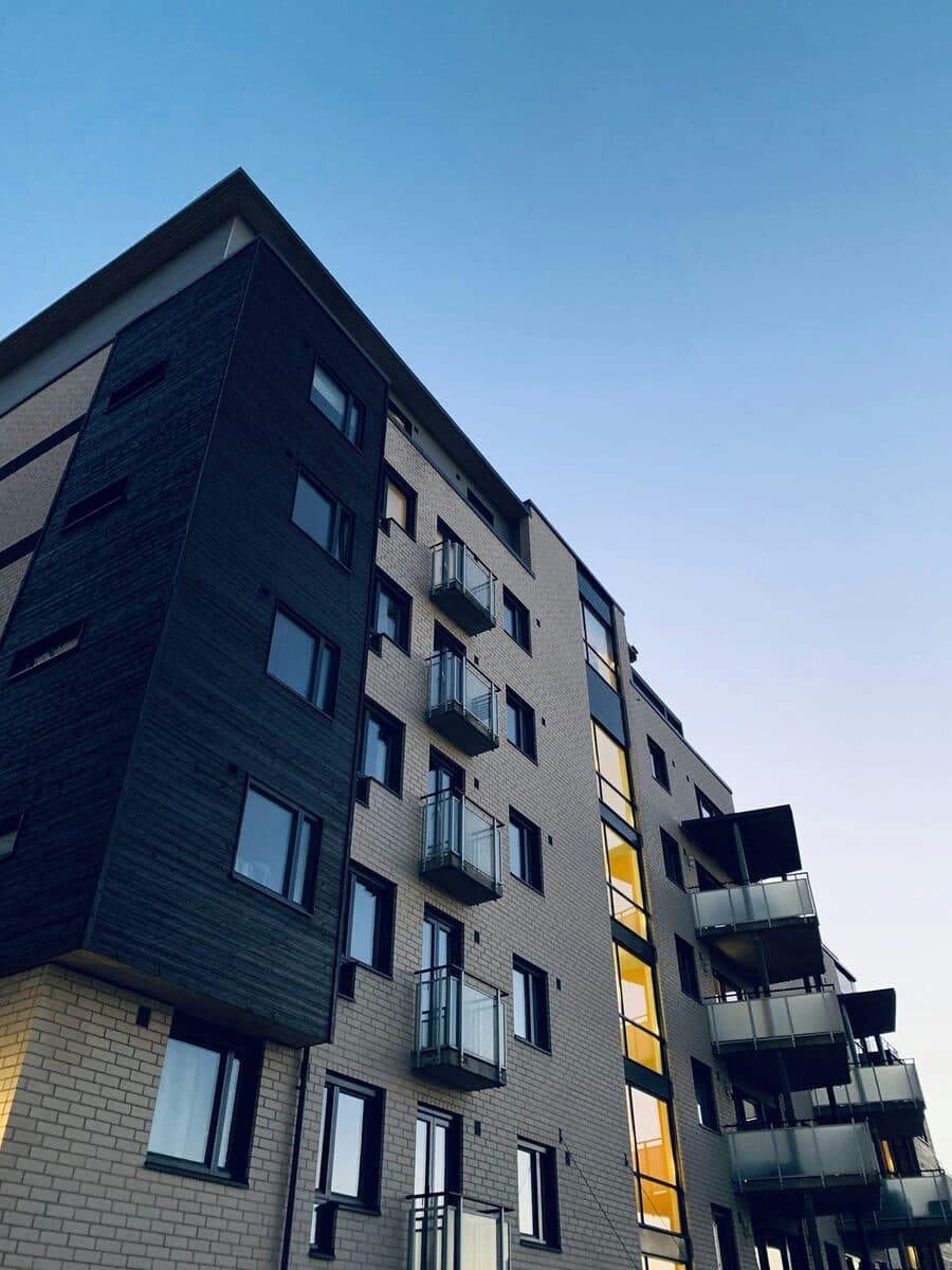
Veritas Facade capability
Elevation and 3D mapping
Locate facade findings against elevations, zones, drops and 3D context so stakeholders can see where work is needed without reconstructing drawings from memory.
Elevation and 3D mapping give each facade finding a place in the building, not only a description. Veritas Facade supports location references such as elevation, zone, BMU drop and window position, and can connect defects into the broader 3D and point-cloud context used for stakeholder review.
Owners and facility managers rarely want a paragraph that says "north elevation, mid-level crack." They want a navigable place in the record. Mapping is how the inspection becomes usable for budgeting, contractor briefing and year-on-year comparison.
When LiDAR or photogrammetry packages are commissioned, the same defect record can sit against the visual model rather than living only in a PDF appendix.
The problem this solves
Without location discipline, defect registers become hard to brief. Contractors bid against ambiguous notes, engineers re-walk areas already inspected, and boards struggle to understand concentration of risk.
Scattered photos without elevation or zone context also make it difficult to prove that a later repair closed the same finding that was originally recorded.
Workflow narrative
- 1. Establish building geometry context
Confirm elevations, zones and access drops relevant to the inspection scope.
- 2. Pin findings to locations
Attach each defect to elevation, zone, drop or window references during capture or review.
- 3. Review in spatial context
Use mapped locations and, where available, 3D or point-cloud views to communicate concentration and access implications.
- 4. Carry locations into remediation
Preserve location references when findings become remediation packages so contractors inherit the same context.
In the product
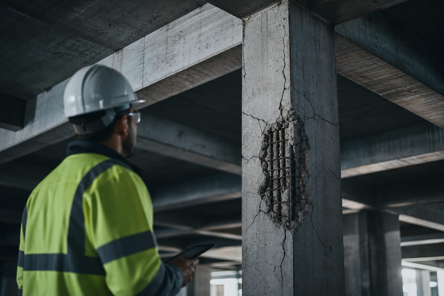
Verified product evidence
Outcomes
- Faster contractor and engineer briefing
- Clearer risk concentration by elevation or zone
- Better continuity between inspections over time
- Less ambiguity in remediation scopes
Applicable standards
- AS 4349.0:2007Inspection of buildings - general requirements
- AS/NZS 4284:2008Testing of building facades
- Project survey controlSite-specific elevation and drop naming conventions
Limitations
3D package dependency
Interactive 3D and point-cloud depth depend on commissioned scanning or photogrammetry packages, which are scoped separately.
Naming consistency
Elevation and drop naming must be agreed early or mapped findings become inconsistent across crews.
FAQ
Common questions
Do we need LiDAR to use location mapping?
Can clients see mapped defects?
How does this help remediation?
Is every building modelled in 3D automatically?
Related Facade capabilities
Mobile defect capture
Record facade defects in the field with structured severity, location context and photo evidence that flows straight into the inspection record.
Inspection reports
Turn structured facade findings into professional reports, with optional engineering review pathways where the engagement requires it.
Remediation workflows
Move facade findings from identified defects into packaged remediation work with progress tracking and closeout evidence.
Client portal
Provide authorised clients with portal access to inspection records and shared views instead of relying only on emailed PDFs.
Book a demo of Elevation and 3D mapping
See this capability in the live Veritas Inspect workspace. Workspace provisioning is operator-led after commercial setup.